Fresnel formulae
baptiste Auguié
04 March, 2017
Single interface
Let us consider the situation depicted below,
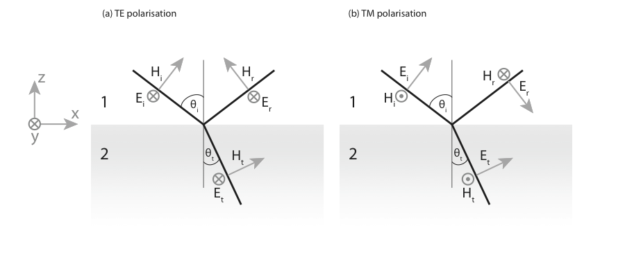
Schematic of reflection and transmission by a single interface. Note that the orientation of the vectors has been chosen so as to have a consistent picture at normal incidence.
where we define the Fresnel coefficients as the ratio of the complex amplitude of the electric fields, \(r= E_r/E_i\) for the reflection coefficient, and \(t= E_t/E_i\) for the transmission coefficient. The Fresnel coefficients can be obtained by considering the continuity of the tangential component of the \(E\) and \(H\) fields at the interface. The continuity of the normal components of \(D\) and \(B\) does not yield supplementary conditions and will not be considered. It is worth noting that the continuity of \(H^y\) is only valid for materials that do not sustain a surface current resulting from the addition of external charges.
TE-polarised light
For TE-polarised light, the continuity of \(E^y\) reads, \[ E_i + E_r = E_t \] which yields, \[ 1+r =t. \] The continuity of \(H^x\) can be written as, \[ H_i\cos\theta_i - H_r\cos\theta_i = H_t\cos\theta_t \] It is convenient to express the angles in terms of the normal component of the \(k\)-vectors, \[ k_z = n k_0 \cos\theta. \] for the incident, reflected, and refracted fields, so that \(\cos\theta_t / \cos\theta_i=\dfrac{k_{z2}n_1}{k_{z1}n_2}\). The complex magnitude of the magnetic and electric fields are linked in each medium by the optical impedance. Its expression can be obtained from the induction law in a homogeneous medium, \[ \nabla\times\mathbf{E} = -\partial_t \mathbf{B} \] expressed in Fourier space as, \[ \mathbf{k}\times \mathbf{E} = i\omega \mathbf{B} \] The ratio \(E/H\) is the impedance, written as, \[ \frac{E}{H}= c \mu \mu_0 / n= \sqrt{\frac{\mu\mu_0}{\varepsilon\varepsilon_0}}=Z\cdot Z_0. \] We can define the admittance \(Y\) as the inverse impedance, \(Y=\dfrac{1}{Z\cdot Z_0}\) The continuity of \(H^y\) can be expressed as, \[ Y_1 (1 - r) = Y_2 \frac{n_1k_{z2}}{n_2k_{z1}}t. \] After rearranging, we obtain, \[ 1 - r = \frac{\mu_1k_{z2}}{\mu_2k_{z1}}t. \] We can summarize the two continuity relations in the following system,
\[\left\{ \begin{aligned} 1 + r &= t\\ 1 - r &= \frac{\mu_1 k_{z2}}{\mu_2 k_{z1}}t \end{aligned}\right. \] Solving for \(r\) and \(t\) yields the result, \[ t_{12}^s=\frac{2\mu_2 k_{z1}}{\mu_2 k_{z1}+\mu_1k_{z2}},\qquad r_{12}^s=\frac{\mu_2 k_{z1}-\mu_1k_{z2}}{\mu_2 k_{z1}+\mu_1k_{z2}}. \]
TM-polarised light
For TM-polarised light, it is generally easier to consider the Fresnel coefficients for the magnetic field, denoted \(\rho\) and \(\tau\). The continuity of \(H^y\) reads, \[ 1 - \rho = \tau \] The continuity of \(E^y\) can be written, \[ \frac{k_{z1}}{\varepsilon_1} + \rho \frac{k_{z1}}{\varepsilon_1} = \tau \frac{k_{z2}}{\varepsilon_2} \]
We can summarize the two continuity relations in the following system,
\[\left\{ \begin{aligned} 1 - \rho &=\tau\\ (1 + \rho) \frac{k_{z1}}{\varepsilon_1}&=\frac{k_{z2}}{\varepsilon_2}\tau \end{aligned}\right. \] Solving for \(\rho\) and \(\tau\) yields the result, \[ \tau_{12}^p=\frac{2\varepsilon_2 k_{z1}}{\varepsilon_2 k_{z1}+\varepsilon_1k_{z2}},\qquad \rho_{12}^p=\frac{\varepsilon_2 k_{z1}-\varepsilon_1k_{z2}}{\varepsilon_2 k_{z1}+\varepsilon_1k_{z2}}. \]
To summarize, for a single interface from 1 to 2 with normal along the \(z\) direction, the Fresnel coefficients read, \[ \begin{aligned} \rho_{12}^p&=\frac{\varepsilon_2 k_{z1}-\varepsilon_1k_{z2}}{\varepsilon_2 k_{z1}+\varepsilon_1k_{z2}},&{}& r_{12}^s=\frac{\mu_2 k_{z1}-\mu_1k_{z2}}{\mu_2 k_{z1}+\mu_1k_{z2}}\\ \tau_{12}^p&=\frac{2\varepsilon_2 k_{z1}}{\varepsilon_2 k_{z1}+\varepsilon_1k_{z2}},&{}& t_{12}^s=\frac{2\mu_2 k_{z1}}{\mu_2 k_{z1}+\mu_1k_{z2}}. \end{aligned} \]
Note that, \[ r_{ij}=-r_{ji}. \] To verify the conservation of energy, one must consider the irradiance defined in terms of the electric field as \(I=\frac{1}{2}Y|E|^2\), yielding, \[ R=\frac{I_r}{I_i}=|r|^2, \qquad T=\frac{I_t}{I_i}=\frac{Y_1}{Y_2}|t|^2. \] and we can verify that, indeed, \(R+T=1\) for a single interface.
Reflectivity of a layer
From the viewpoint of ray optics, a thin layer will support an infinite number of internal reflections (absorption and irregularities will however reduce the intensity in a physical situation). The infinite series of reflected orders can be expressed in the form a geometric sum, leading to a closed form formula as shown below.
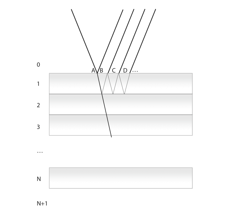
Schematic of reflection and transmission by a multilayer stack. A few reflected orders are noted A, B, C and D for the first film.
An incident plane wave with amplitude \(A\) impinges on the first interface. It can be reflected, \(B=r_{01}A\), or transmitted. The total response of the slab can be obtained by following each order of reflection inside the slab (C, D, \(\dots\)).
Upon transmission at the first interface, the wave amplitude is \(t_{01}A\). Application of Fermat’s principle yields a phase change \(\Delta \phi= k_{z1}d\) when the wave hits the second interface. The reflection coefficient at this interface is \(r_{12}\). The partial wave reflected from this path, noted C, is therefore \(C=t_{10}t_{01}r_{12}\exp(2i k_{z1}d)A\).
Similarly, in D, \[
D=t_{10}t_{01}r_{10}r_{12}^2\exp(4i k_{z1}d)A
\] And, for the \({j^\text{th}}\) partial wave, \[
t_{10}t_{01}r_{12}^{j}r_{10}^{{j-1}}\exp(2i {j}k_{z1}d)A
\] The wave reflected by the slab is the sum of these contributions, \[
r_{\text{slab}}A=B+C+D+\dots=\left[r_{01}+t_{10}t_{01}r_{12}\sum_{j=0}^{\infty}r_{12}^jr_{10}^{j}\exp(2ji k_{z1} d)\right]A
\] For clarity, I write \(\beta=r_{12}r_{10}\exp(2i k_{z1}d)\). The summation of all partial waves is thereby expressed as a geometrical sum, \[
r_{\text{slab}}=r_{01} + \left(t_{10}t_{01}r_{12}\exp(2i k_{z1}d)\right)\sum_{j=0}^{\infty}\beta^j
\] Recalling that the sum of a geometric series of common ratio \(q\) is \(\frac{1}{1-q}\), we can write, \[
r_{\text{slab}}=r_{01} + \frac{t_{10}t_{01}r_{12}\exp(2i k_{z1}d)}{1-r_{12}r_{10}\exp(2i k_{z1}d)}
\]
We note that for either polarisation we have the following identity, \[ t^s_{ij}t^s_{ji} = (1-r^s_{ij})(1+r^s_{ij})= 1-(r^s_{ij})^2 ,\qquad t^p_{ij}t^p_{ji} =\frac{Y_i}{Y_j}(1-r^p_{ij})\frac{Y_j}{Y_i}(1+r^p_{ij}) = 1-(r^p_{ij})^2 \] Using this equation and the substitution \(r_{10} = -r_{01}\) we finally obtain, \[ r_{\text{slab}}=\frac{r_{01}+r_{12}\exp(2i k_{z1}d)}{1+r_{01}r_{12}\exp(2i k_{z1}d)}. \]
For the transmission, one obtains,
\[ t_{\text{slab}}=\frac{t_{01}t_{12}\exp(i k_{z1}d)}{1+r_{01}r_{12}\exp(2i k_{z1}d)}. \]
Reflectivity of a multilayer structure
When N layers are stacked together, the reflection coefficient of the structure can be found by applying recursively the preceding formula for a single layer. This amounts to considering one of the reflection coefficients to be the effective reflection accounting for all the layers behind. Let us consider explicitly the case of a 3 layer system. The procedure is as follows,
- Compute and store for later use all single-interface coefficients, namely \(r_{01}\), \(r_{12}\), \(r_{23}\), \(r_{34}\)
- Combine the previous coefficients to compute the reflectivity of the last layer, i.e. \(r_{24} = \frac{r_{23}+r_{34}\exp(2i k_{z3}d_3)}{1+r_{23}r_{34}\exp(2i k_{z3}d_3)}\). This value can be stored in a temporary variable \(r_{\text{tmp}}\)
- Go up, combining one interface at a time, \(r_{\text{tmp}}=r_{14} = \frac{r_{12}+r_{24}\exp(2i k_{z2}d_2)}{1+r_{12}r_{24}\exp(2i k_{z2}d_2)}\)
- the combined reflectivity of the multilayer is obtained when one has reached the top interface, \(r_{\text{tmp}} = r_{04} = \frac{r_{01}+r_{14}\exp(2i k_{z1}d_1)}{1+r_{01}r_{14}\exp(2i k_{z1}d_1)}\)